Functions of Engine Coolant Temperature Speed Sensors
Abstract:
As a user of emergency power systems, it is essential to understand the common sensor types, structures, and working principles of diesel engines. Key sensors include speed sensors, temperature sensors, oil pressure sensors, and coolant level sensors. Operators must master detection procedures for each sensor and accurately assess their functionality and responsiveness based on the diesel generator’s operating conditions. This prevents sensor failures that could trigger false alarms.
The basic principle is as follows: When the starter switch is activated, the automatic protection system powers up and performs a self-check to verify sensor status. Once completed, the system enters normal operation. During runtime, if a sensor detects a value exceeding preset thresholds, operators must promptly diagnose and resolve the issue. If unresolved, the protection system will initiate a forced shutdown.
I. Key Components of Sensors
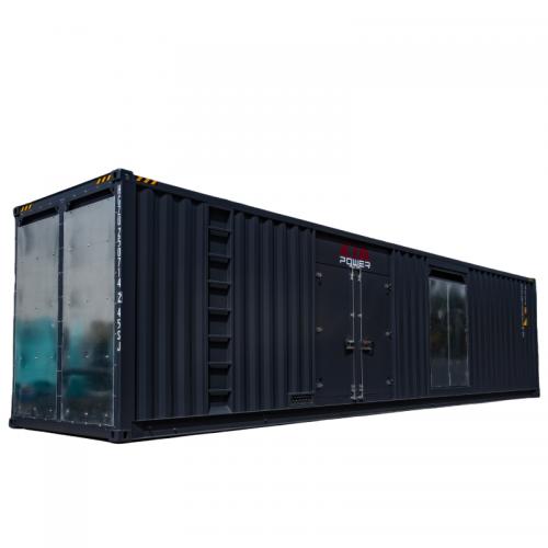
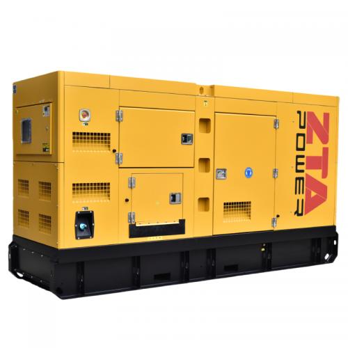
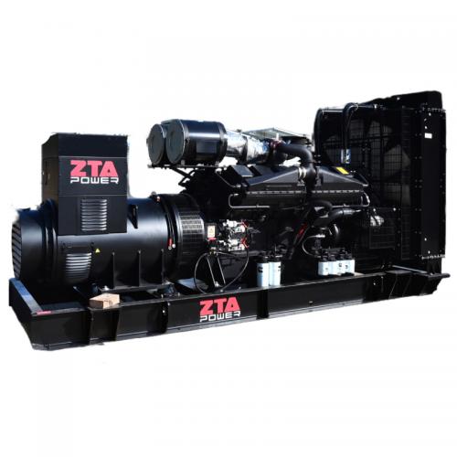
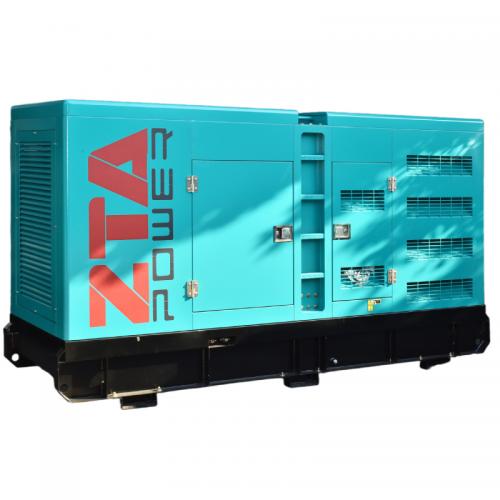
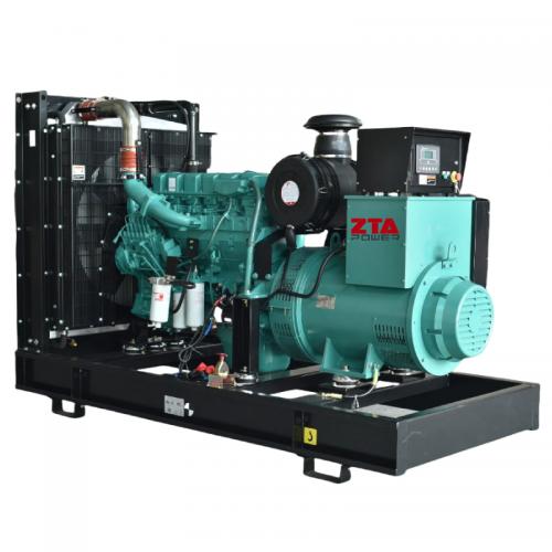
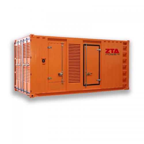
Automated diesel generators typically use three core sensors: oil pressure sensors, temperature sensors, and speed sensors, with some models additionally equipped with coolant level sensors (see Figures 1 and 2 for installation positions). Diesel engine sensors generally consist of three components:
Sensitive Element
Directly interacts with the measured parameter (e.g., temperature, pressure) and outputs a corresponding physical signal. Non-electrical parameters often require preliminary conversion. Sensitive elements, such as elastic diaphragms or bimetallic strips, act as pre-transducers.
Transduction Element
Converts the output of the sensitive element into an electrical parameter (voltage, current, or frequency). Examples include:
Resistance strain gauges (for pressure detection)
Hall elements (for speed/magnetic field detection)
Signal Conditioning Circuit
Processes electrical parameters into standardized outputs (e.g., 4–20 mA, 0–5 V). Common circuits include:
Amplifiers
Wheatstone bridges
Oscillators
Impedance converters

Coolant Temperature Sensor (CTS)
The Coolant Temperature Sensor (CTS), also known as the Engine Coolant Temperature (ECT) sensor, is a thermistor-based device where resistance decreases as temperature rises and increases as temperature drops. It is installed in the water jacket of the diesel engine cylinder block or cylinder head, directly contacting the coolant to monitor its temperature. Typically mounted on the engine’s coolant outlet housing, the CTS triggers audible/visual alarms via the automatic protection system when coolant temperature exceeds 95°C.
1. Types of Temperature Sensors
Temperature sensors for diesel generators fall into four categories
Thermistor-type sensors (most common)
Thermistor ferrite sensors
Wax pellet-type sensors
Bimetallic strip-type sensors
Thermistor-type sensors are fabricated by sintering ceramic semiconductor materials mixed with metal oxides into high-temperature-coefficient resistors. Based on their resistance-temperature characteristics, thermistors are classified into three types (see Figure 3):
Negative Temperature Coefficient (NTC) Thermistors: Resistance decreases as temperature increases.
Positive Temperature Coefficient (PTC) Thermistors: Resistance increases with rising temperature.
Critical Temperature Resistor (CTR) Thermistors: Exhibit abrupt resistance changes at a specific critical temperature.
2. Function
The CTS detects engine operating temperature and transmits coolant temperature signals to the Engine Control Unit (ECU). These signals are used to:
Adjust fuel injection timing and duration (e.g., increased fuel during cold starts for smoother operation).
Optimize ignition timing for combustion efficiency.
3. Installation Location
The CTS is installed in the engine’s water jacket (cylinder block/head) or thermostat housing, extending into the coolant flow (see Figure 4)

4. Working Principle
The Coolant Temperature Sensor (CTS) is primarily constructed using a Negative Temperature Coefficient (NTC) thermistor, which exhibits decreasing resistance as temperature increases and vice versa. At low coolant temperatures, the sensor’s resistance is high; as temperatures rise, resistance decreases. The sensor’s structure and resistance-temperature characteristics are illustrated in Figure 5.
The CTS connects to the Engine Control Unit (ECU) via a two-terminal wiring harness:
Signal Wire: Transmits a voltage signal that varies with the thermistor’s resistance. The ECU calculates coolant temperature based on this voltage fluctuation.
Ground Wire: Provides a reference path for the circuit (see Figure 6).


 IPv6 network supported
 English
 français
 русский
 español
 português
 العربية
 Türkçe
 ไทย
ไทย Tiếng Việt
 Indonesia
  Filipino